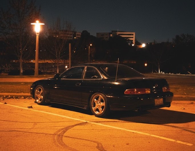
The Lexus SC400 is one of the most compelling platforms for a manual transmission conversion. A silky 1UZ-FE V8, a well-balanced rear-wheel-drive chassis, a relatively light body, and enough aftermarket support to make serious power — it's a legitimate sports car held back by an automatic gearbox that most enthusiasts find inadequate for performance driving. The CD009 6-speed from the Nissan 350Z and G35 has become the go-to solution, and for good reason: it's strong, it adapts to the 1UZ-FE bellhousing with commercially available adapter plates, and it's proven in high-power builds across the country.
But the mechanical side is only half the story. Once you've sourced the transmission, adapter plate, driveshaft, and pedal assembly, you still have to solve the wiring — and the SC400's wiring is where a lot of otherwise excellent builds fall apart. This guide covers everything you need to know about the electrical side of a CD009 swap in the SC400, including what changes, what options you have, and how to plan the build properly from the start.
Why the CD009 Is the Right Choice
Before getting into the wiring details, it's worth understanding why the CD009 became the standard for SC400 manual swaps. The R154 5-speed from the Supra and other Toyota applications is another option, but the CD009 offers several practical advantages. It's a 6-speed with better gear spacing for performance driving. It's stronger than the R154 in stock form. And the input shaft diameter is compatible with adapter plate solutions that allow direct attachment to the 1UZ-FE bellhousing without custom fabrication.
The CD009 also uses a hydraulic clutch system, which simplifies the pedal conversion since you're working with fluid lines rather than a mechanical linkage. That said, the hydraulic circuit needs to be routed and plumbed correctly — and the master cylinder location matters for pedal feel. This is purely mechanical, not electrical, but it's part of the overall swap picture.
Where the wiring becomes relevant is in how the CD009 communicates with the rest of the vehicle — and how the absence of the A650E automatic transmission changes what the factory ECU expects to see.
What the A650E Does in the Electrical System
The stock SC400 is built around the A650E 4-speed automatic. From an electrical standpoint, the A650E is deeply integrated into the factory ECU and body electrical system. The ECU sends shift commands to the transmission, the transmission reports gear position back to the ECU, and the throttle strategy — including rev-matching behavior and torque reduction requests during shifts — is built around automatic transmission operation.
Beyond the ECU, the A650E connects to the range sensor (what most people call the neutral safety switch) to prevent the engine from cranking in gear, to the speedometer via the vehicle speed sensor, and to the transmission control module for overdrive lockup operation. When you remove the automatic and replace it with a manual, all of those interfaces need to be addressed. You can't simply unplug the A650E and bolt in a CD009 — the factory ECU will throw codes, and some of those codes will prevent the car from starting or running correctly.
The Neutral Safety Switch Problem
The neutral safety switch in the SC400's A650E allows the starter circuit to complete only when the range selector is in Park or Neutral. When you remove the automatic and go manual, that circuit is gone — and the starter won't crank unless you address it.
You have two options. The simple approach is to jumper the neutral safety circuit, bypassing the switch entirely so the starter will always crank regardless of clutch position. This works but removes a safety feature — the car can now be cranked in gear without the clutch depressed, which is generally undesirable.
The better approach is to wire in a clutch switch that replaces the neutral safety logic. A properly wired clutch switch allows the car to crank only when the clutch pedal is fully depressed, mimicking the safety behavior of the original system while being correct for a manual transmission. If you're running a standalone ECU, this integration is straightforward — the ECU has a dedicated start enable input that you wire directly to the clutch switch. The ECU handles the logic, and you have full control over whether start requires the clutch, whether it's required under all conditions, and how the feature behaves on the track.
VSS Integration: Matching the Signal
Vehicle speed sensor integration is one of the most commonly overlooked wiring challenges in the CD009 swap. The A650E outputs a speed signal that the ECU uses for fuel and ignition corrections, and that the gauge cluster uses for the speedometer. The CD009 has its own VSS, but it outputs a different signal — different pulse rate, different voltage characteristics, and potentially different connector pinout.
If you're running the factory ECU, you'll need to either add a signal conditioner to translate the CD009 VSS output to something the factory system understands, or recalibrate the speedo separately. Neither solution is particularly clean. The signal conditioner approach adds a device to the harness that needs to be mounted somewhere and powered, and it adds another potential failure point.
Running a standalone ECU solves this cleanly. Every major standalone ECU platform — Haltech, Link, MaxxECU, EMU Black — has a configurable VSS input. You tell the ECU how many pulses per revolution the CD009 VSS sends, and the ECU handles the math. The speedometer can be driven from the ECU's VSS output, recalibrated to match actual speed. It's a complete solution that doesn't require any additional devices. If you're deciding between factory ECU and standalone, the VSS situation alone is a strong argument for going standalone. See our guide on choosing a standalone ECU for a full breakdown of the available platforms.
Reverse Lights
The reverse light circuit is a straightforward change but one that's easy to forget in the middle of a complex swap. The A650E doesn't have a traditional reverse light switch — reverse gear is handled through the range sensor, and the ECU or body control module handles the reverse light output based on range sensor position.
The CD009 has a conventional reverse light switch mounted in the transmission housing. You need to wire this switch into the SC400's reverse light circuit. The switch is normally open and closes when the transmission is shifted into reverse, completing the circuit and illuminating the reverse lights. The exact wiring path depends on whether you're keeping the factory body electrical system or doing a more comprehensive rewire, but the fundamental task is the same: find the reverse light power feed in the SC400 chassis harness and connect it through the CD009 reverse switch.
If you're running a standalone ECU, the reverse switch can also be wired to an ECU input so the ECU can track reverse gear selection — useful for features like rear camera triggers, reverse speed limiters, or launch control disabling logic.
Cruise Control and Throttle Strategy
The factory SC400 cruise control system is integrated with the automatic transmission's throttle strategy. The A650E and cruise control communicate to manage throttle position during gear changes, maintain speed on grades, and limit engine output during transmission shifts. When you remove the automatic, the cruise control logic becomes problematic.
In most CD009 swap builds, factory cruise control is either deleted entirely or re-implemented through the standalone ECU. The factory system, which uses a servo motor and cable to control throttle position, can technically still function with a manual transmission, but the integration with the factory ECU becomes inconsistent when the ECU is also seeing fault codes from the missing automatic transmission. The cleanest solution is to delete factory cruise and implement cruise control through the standalone ECU using a cruise switch and the ECU's built-in speed control logic.
Standalone ECU: The Right Foundation for the CD009 Swap
Running a standalone ECU in a CD009-swapped SC400 isn't just about solving the wiring challenges described above — it's about building the car correctly for what you're actually going to do with it. A standalone ECU gives you complete control over engine management: ignition timing, fuel maps, idle control, boost control if you're adding forced induction, traction control, launch control, and more. The factory ECU in the SC400 was calibrated for a specific power level, a specific transmission, and street use. It is not a performance tuning tool.
More practically, a standalone ECU eliminates the chain of dependencies that makes the factory wiring so complex to adapt. You no longer need to interface with the OEM transmission control, satisfy the A650E's communication requirements, or work around the factory ECU's error detection logic. The standalone ECU talks to your sensors, drives your outputs, and does exactly what your tune tells it to do.
For SC400 builds targeting anything beyond mild street use, the standalone ECU is the correct choice. Budget for it from the start rather than trying to add it later after fighting the factory system for months.
Our SC300/SC400 Standalone Harness
Our standalone harness for the SC300 and SC400 is built specifically to handle the CD009 conversion and standalone ECU integration. Every interface point described in this article — the neutral safety/clutch switch, VSS integration, reverse light switch, and standalone ECU connectors — is addressed in the harness design.
We build to your specific ECU choice. Whether you're running a Haltech Elite, Link G4X, MaxxECU, or another platform, the harness is configured for that ECU's connector layout and pinout. Connectors are Deutsch DT series throughout, wiring is TXL cross-linked polyethylene or Raychem Spec 44 depending on location, and every circuit is labeled for installation.
We also account for your transmission choice specifically. If you're running the CD009, the harness includes the reverse switch circuit, VSS wiring, and clutch switch input for the standalone ECU. If your build includes additional modifications — additional sensors, data logging, boost control — we configure the harness to accommodate those as well.
The result is a harness where you're not adapting something that wasn't designed for your build. Everything connects cleanly, and the car starts, runs, and drives the way a properly built manual-swapped SC400 should. Contact us with your build details to get a quote.
Planning Your CD009 Swap: Wiring Considerations
If you're in the planning stages of a CD009 swap, a few notes on sequencing that will save you time and money:
Decide on your ECU before finalizing the harness. The harness is configured for your specific ECU, and changing ECU platforms after the fact means a different harness configuration. Make the ECU decision early, even if the ECU purchase comes later in the build.
Order your harness and ECU together or with the mechanical parts. The harness build time at SVK Works is typically 4–6 weeks. Starting the harness order early in the mechanical side of the build means both will be ready at roughly the same time, and you won't have a completed mechanical swap sitting idle waiting on wiring.
Consider the full electrical picture. If you're installing a standalone ECU, you're also dealing with sensors — wideband O2 sensor, intake air temperature, coolant temperature, oil pressure, and potentially knock. Make a list of everything the ECU needs to read and verify you have sensor bungs in all the right places before the engine goes in. Adding sensor bungs to an installed exhaust or intake manifold is much harder than doing it on the bench.
Verify your fuel system. The 1UZ-FE in the SC400 uses a returnless fuel system in some configurations. Standalone ECU with injector control sometimes requires a return-style fuel system for proper fuel pressure regulation. Confirm this with your tuner before purchasing or ordering the harness so any necessary fuel system changes are factored in.